
Should I use heat set inserts in thin-wall 3D printed parts? Heat set inserts can be used in thin-wall 3D printed parts only when the insert area is locally reinforced with enough wall thickness, boss diameter, edge distance, and support geometry. They should not be installed directly into a thin unsupported wall without extra plastic around the insert.
A heat set insert needs surrounding plastic to grip the knurled outer surface. If the wall is too thin, the insert may crack the part, deform the wall, spin during screw tightening, or pull out under load. Thin-wall parts can work with inserts, but the wall usually needs a boss, rib, thickened pad, or local reinforcement.
The question is not simply whether the part is thin. The real question is whether the insert location has enough printed material to support heat, torque, screw preload, and the real load path.
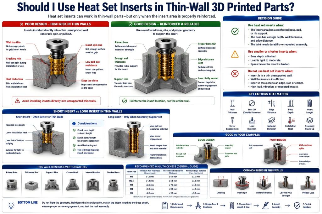
Short Answer
Use heat set inserts in thin-wall parts only if the insert zone is reinforced. Do not place an insert directly into a flat thin wall unless the load is very light and the geometry has been tested.
| Thin-Wall Situation | Insert Decision | Better Design Action |
|---|---|---|
| Thin wall with no reinforcement | Usually avoid | Add a boss, pad, rib, or thicker local area. |
| Thin enclosure wall with raised boss | Often acceptable | Check boss OD, wall thickness, and screw engagement. |
| Insert close to edge or corner | High risk | Move the insert inward or add supporting geometry. |
| Low-load cosmetic cover | Possible with testing | Use small inserts and controlled torque. |
| Load-bearing thin bracket | Usually redesign | Create a stronger boss and load path. |
Why Thin Walls Are Difficult for Heat Set Inserts
A heat set insert is installed by heating the insert and pressing it into plastic. The surrounding plastic softens, flows around the insert knurls, and then cools into a mechanical lock.
A thin wall has limited plastic volume. That means it has less material to absorb installation heat, less wall thickness to resist radial expansion, and less structure to resist screw torque or pull-out load.
Thin-wall insert problems often come from:
- not enough plastic around the insert body
- insert placed too close to the wall surface
- boss outside diameter too small
- edge distance too short
- installation heat deforming the wall
- screw preload bending the wall
- insert knurls breaking through the side
- thin layers splitting around the hole
For wall thickness planning, see Heat Set Insert Minimum Wall Thickness Reference for 3D Printed Parts.
Thin Wall Does Not Mean No Inserts
A thin-wall part can still use heat set inserts if the insert location is designed as a reinforced feature. The mistake is treating the wall itself as the boss.
Better thin-wall insert designs often use:
- raised bosses on the inside of the wall
- local thickened pads around screw locations
- ribs connecting the insert boss to the main body
- corner blocks or reinforced mounting towers
- larger flat pads under screw heads
- shorter inserts where depth is limited
- smaller screw sizes when load is light
- moved insert locations with more edge distance
The goal is to create enough local plastic support without making the entire part thick.
When Heat Set Inserts Are Acceptable in Thin-Wall Parts
Heat set inserts may be acceptable in thin-wall parts when the local insert area is reinforced and the load is realistic for the geometry.
They may work when:
- the insert sits in a raised boss or thickened pad
- the boss has enough outside diameter
- there is enough wall thickness around the insert
- the insert is far enough from edges and corners
- the screw only carries light to moderate clamp load
- the part is not heavily vibration-loaded
- the screw will not be overtightened
- the material can tolerate installation heat
- the design has been tested with the final insert and screw
For boss design, see How to Design Bosses for Heat Set Inserts and Boss OD Ratio for Heat Set Inserts in 3D Printed Parts.
When Heat Set Inserts Are Not Recommended
Heat set inserts are risky when the printed wall is asked to act like a structural boss without enough material around the insert.
They are usually not recommended when:
- the insert is placed directly in a thin flat wall
- the wall is thinner than the insert requires
- the insert is close to an edge, slot, or corner
- the boss outside diameter is too small
- the insert may break through the side wall
- the screw needs high preload
- the joint carries structural load
- the part sees vibration or repeated impact
- the wall can flex under screw tightening
- the boss has weak layer orientation
For related failure behavior, see Why Do Heat Set Inserts Fail in Thin Wall 3D Printed Parts? and Why Do Heat Set Inserts Fail Near Edges or Corners?.
Small Inserts Are Not Automatically Safe
One common reaction is to choose a smaller insert for a thin wall. This can help in some cases, but it does not automatically solve the problem.
A smaller M2 or M2.5 insert still needs enough plastic around it. If the wall is too thin, the insert can still crack the boss, spin under screw torque, or break through the side. The smaller screw also provides less preload and less thread engagement.
Use smaller inserts when the load is light and the boss can support them. Do not use smaller inserts as a disguise for missing wall thickness.
For small insert selection, see M2 Brass Heat Set Inserts for 3D Printed Parts and Should I Use M2.5 or M3 Heat Set Inserts in 3D Printed Parts?.
Boss Design for Thin-Wall Parts
In thin-wall parts, the boss should do most of the fastening work. The wall should not be the only structure resisting insert expansion, screw torque, or pull-out load.
A good thin-wall insert boss should provide:
- enough boss outside diameter
- enough wall thickness around the insert
- a flat seating surface
- support ribs back to the main wall or base
- fillets where the boss meets the wall
- enough depth for insert seating
- enough screw engagement
- clearance from edges, cutouts, and corners
- a load path that does not bend the wall
A thin wall with a proper boss is often workable. A thin wall without a boss is a little paper bridge pretending to be a pier.
Edge Distance Matters More in Thin Walls
Thin-wall parts often place inserts close to edges because there is limited space. This increases risk. When an insert is close to an edge, screw load and installation stress can break through the shortest wall path.
Edge distance is especially important near:
- corners
- enclosure lips
- thin flanges
- mounting tabs
- slot edges
- cutouts
- hinge bosses
- snap-fit features
For edge planning, see Heat Set Insert Edge Distance Reference for 3D Printed Parts.
Short Inserts May Be Better Than Long Inserts
Thin-wall parts often cannot support long inserts. A long insert may require more heat, deeper seating, and more boss depth. If the part is shallow, the insert may bottom out, bulge the underside, or weaken the surrounding wall.
Short inserts may be better when:
- boss depth is limited
- the load is light to moderate
- the wall cannot tolerate deep heating
- the screw does not need long engagement
- the part has limited clearance below the insert
Long inserts may work only when the boss is deep, reinforced, and not close to thin surfaces.
For insert length selection, see Should I Use Short or Long Heat Set Inserts in 3D Printed Parts?, Short vs Long Heat Set Inserts for 3D Printed Parts, and Heat Set Insert Hole Depth Chart for 3D Printed Parts.
Material Choice Changes the Risk
Material behavior affects whether thin-wall inserts survive installation and use. Some materials crack easily around small features. Others deform, creep, or relax under screw preload.
| Material | Thin-Wall Insert Behavior | Design Note |
|---|---|---|
| PLA | Stiff but brittle around thin bosses | Avoid tight holes, sharp corners, and overtightening. |
| PETG | Tougher but may deform or relax under preload | Use reinforced bosses and check screw preload over time. |
| ABS / ASA | Can work well if printed with good layer adhesion | Control installation heat and avoid thin unsupported walls. |
| Nylon | Tough but may creep under sustained load | Use mechanical support and avoid relying only on clamp force. |
| Fiber-filled materials | Stiff but can be less forgiving near thin walls | Use fillets, ribs, and careful pilot hole testing. |
For material comparison, see PLA vs PETG vs ABS for Threaded Inserts and Layer Adhesion and Heat Set Insert Strength in 3D Printed Parts.
Installation Heat Can Distort Thin Walls
Thin walls are more sensitive to installation heat. The heat from the insert can soften not only the boss, but also nearby wall surfaces, edges, or cosmetic features.
Common heat-related risks include:
- wall bulging near the insert
- boss sinking too deep
- insert tilting during installation
- plastic pushing through the wall
- surface distortion on the outside of an enclosure
- hole becoming oversized after overheating
- thin features warping near the insert
For installation control, see Heat Set Insert Installation Temperature for 3D Printed Parts and Heat Set Insert Seating Depth Reference for 3D Printed Parts.
Screw Preload and Thin-Wall Flex
A thin wall may flex under screw preload even if the insert itself holds. This can reduce clamp force, shift the mating part, or create stress around the boss.
This is common in:
- thin electronics enclosures
- small access covers
- thin mounting tabs
- lightweight brackets
- printed shells
- thin battery covers
- sensor housings
If screw preload bends the wall, the insert may not be the only problem. The surrounding geometry may need a rib, thicker pad, washer seat, or better load path.
For preload behavior, see Why Does Screw Preload Drop in 3D Printed Insert Joints?.
Common Mistakes
- installing an insert directly into a thin flat wall
- choosing a small insert without checking wall thickness
- placing inserts too close to edges or corners
- using a long insert in a shallow boss
- overheating the boss during installation
- overtightening screws in thin-wall parts
- assuming the insert strengthens the wall by itself
- ignoring screw bottoming and stack-up
- not adding ribs or local thickening
- testing only the first assembly, not repeated service
For hole-size failure behavior, see Why Do Heat Set Inserts Fail When the Hole Is Too Small? and Why Do Heat Set Inserts Fail When the Hole Is Too Large?.
Practical Decision Rule
Use this simple rule:
- Do not place inserts directly into unsupported thin walls.
- Use heat set inserts when the insert location has a reinforced boss, pad, rib, or local thickening.
- Use smaller or shorter inserts only when the load and geometry justify them.
- Redesign the part if the wall cannot provide enough plastic around the insert.
- Test the real material, screw, and installation method before relying on the joint.
A heat set insert needs a home, not just a hole. In thin-wall parts, that home must be built deliberately.
Related Engineering Guides
- How to Choose Heat Set Inserts for 3D Printed Parts
- Heat Set Insert Hole Size Guide
- How to Design Bosses for Heat Set Inserts
- Screw Engagement Length for Heat Set Inserts in 3D Printed Parts
- Heat Set Insert Installation Temperature for 3D Printed Parts
- PLA vs PETG vs ABS for Threaded Inserts
Related Selection Questions
- Should I Use M2.5 or M3 Heat Set Inserts in 3D Printed Parts?
- Should I Use Short or Long Heat Set Inserts in 3D Printed Parts?
- Should I Use Heat Set Inserts or Self-Tapping Screws in 3D Printed Parts?
Related Failure Questions
- Why Do Heat Set Inserts Fail in Thin Wall 3D Printed Parts?
- Why Do Bosses Crack Around Heat Set Inserts?
- Why Do Heat Set Inserts Fail Near Edges or Corners?
- Why Do Heat Set Inserts Fail When the Hole Is Too Small?
- Why Do Heat Set Inserts Fail When the Hole Is Too Large?
Related References
- Heat Set Insert Minimum Wall Thickness Reference for 3D Printed Parts
- Heat Set Insert Edge Distance Reference for 3D Printed Parts
- Heat Set Insert Seating Depth Reference for 3D Printed Parts
- Heat Set Insert Hole Depth Chart for 3D Printed Parts
- Heat Set Insert Assembly Stack-Up Reference for 3D Printed Parts
FAQ
Can heat set inserts be used in thin-wall 3D printed parts?
Yes, but only when the insert area is locally reinforced with enough boss diameter, wall thickness, edge distance, and support geometry. Do not rely on a thin flat wall alone.
What is the biggest risk with inserts in thin walls?
The biggest risk is that the wall does not have enough plastic to support installation heat, insert expansion, screw torque, or pull-out load. This can cause cracking, insert spin, wall distortion, or pull-out.
Should I use smaller inserts in thin-wall parts?
Smaller inserts can help when loads are light, but they still need enough surrounding plastic. A smaller insert does not fix poor wall thickness or weak boss geometry by itself.
Are short inserts better for thin-wall parts?
Often yes. Short inserts can reduce depth and heat-related risk, but they also provide less thread engagement and lower pull-out margin. The choice depends on load, boss depth, and screw engagement.
What should I do if the wall is too thin for an insert?
Add a raised boss, thickened pad, rib, corner block, or local reinforcement. If the load is important, redesign the part instead of forcing an insert into an unsupported thin wall.