
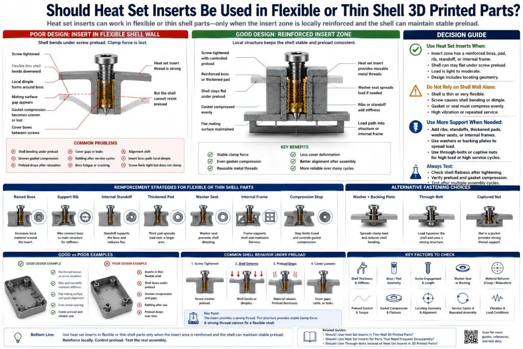
Should heat set inserts be used in flexible or thin shell 3D printed parts? Heat set inserts can be used in flexible or thin shell 3D printed parts, but only when the insert location is locally reinforced and the shell is not expected to carry screw preload by itself. Thin shells can bend, warp, or lose clamp force even when the insert itself is installed correctly.
A heat set insert provides a durable metal thread. It does not automatically make a flexible shell rigid. If the surrounding shell flexes under screw load, the joint may loosen, the cover may lift, the gasket may leak, or the boss may fatigue over repeated service cycles.
In flexible shell designs, the main question is not only “Can the insert hold?” It is also “Can the shell stay stable when the screw is tightened?”
Short Answer
Use heat set inserts in flexible or thin shell parts only when the insert zone has a reinforced boss, pad, rib, internal frame, standoff, washer seat, or backing structure. Do not place inserts directly into flexible shell surfaces and expect the shell to hold stable preload.
| Shell Condition | Insert Decision | Better Design Action |
|---|---|---|
| Thin shell with no local reinforcement | Usually avoid | Add boss, pad, rib, standoff, or internal frame. |
| Flexible cover that opens often | Use with caution | Use inserts plus locating geometry and controlled preload. |
| Thin enclosure with reinforced bosses | Often acceptable | Check boss support, screw length, and cover flatness. |
| Gasketed thin cover | High sensitivity | Use balanced screw spacing and compression control. |
| High-load or vibration shell joint | Usually needs more than inserts | Consider through-bolts, washers, backing plates, or internal frame. |
Flexible Shells Fail Differently Than Thick Bosses
A thick boss usually fails through insert spin, boss cracking, pull-out, or weak wall thickness. A flexible shell can fail even when the insert remains in place.
Common flexible shell problems include:
- cover bowing under screw preload
- thin shell warping near the insert
- mating surfaces no longer sitting flat
- gasket compression becoming uneven
- screw preload dropping after the shell relaxes
- boss base fatigue from repeated flexing
- panel rattling after service cycles
- insert boss pulling the shell into a local dimple
- alignment drift after repeated assembly
This is why flexible shell designs need local stiffness around the insert location.
Thin-Wall vs Thin Shell: What Is the Difference?
A thin-wall problem is mainly about insufficient plastic around the insert body. A thin shell problem is also about bending behavior across the cover, panel, or enclosure wall.
| Design Problem | Main Issue | Typical Fix |
|---|---|---|
| Thin wall | Not enough material around the insert | Add wall thickness, boss OD, or local pad. |
| Thin shell | Panel bends or warps under screw preload | Add ribs, standoffs, internal frame, or broader clamp area. |
| Flexible cover | Cover does not maintain flat contact | Use locating geometry, balanced screws, and controlled preload. |
| Gasketed shell | Uneven compression causes leaks or gaps | Use compression stops, screw spacing, and stiffening features. |
For the wall-thickness side of the problem, see Should I Use Heat Set Inserts in Thin-Wall 3D Printed Parts? and Heat Set Insert Minimum Wall Thickness Reference for 3D Printed Parts.
When Heat Set Inserts Are Acceptable in Thin Shell Parts
Heat set inserts can work well in thin shell parts when the insert is installed into a local structural feature instead of directly into the shell wall.
They may be acceptable when:
- the insert sits in a reinforced boss or standoff
- the boss connects to ribs or an internal frame
- the shell has enough local thickness around the insert
- the screw load is light to moderate
- the cover does not need high clamp force
- the mating surface can stay flat after tightening
- the part has locating geometry to control alignment
- the screw length and seating depth are controlled
- the design is tested after multiple assembly cycles
For boss design fundamentals, see How to Design Bosses for Heat Set Inserts and Boss OD Ratio for Heat Set Inserts in 3D Printed Parts.
When Heat Set Inserts Are Risky in Thin Shell Parts
Heat set inserts are risky when the shell itself is too flexible to maintain clamp force. This can happen even if the insert does not spin or pull out.
They are risky when:
- the insert is placed directly in a flexible shell wall
- the cover bends when the screw is tightened
- the screw pulls the shell into a local dimple
- the mating surface needs to stay flat
- the shell uses a gasket or seal
- the part sees vibration or repeated movement
- the shell material creeps under clamp load
- the insert is close to an edge or corner
- the boss has no rib or frame support
- the part will be opened and closed frequently
For edge-related boundary decisions, see Should Heat Set Inserts Be Used Near Edges or Corners in 3D Printed Parts?.
Why Screw Preload Is Hard to Control in Flexible Shells
Screw preload is the clamping force created when the screw is tightened. In a rigid structure, that preload is more likely to remain stable. In a flexible shell, tightening the screw may bend the shell instead of creating stable clamp force across the joint.
This can cause:
- uneven contact pressure
- local deformation around screw bosses
- cover gaps between screws
- loss of preload after material relaxation
- rattling after repeated service
- gasket compression loss
- misalignment after reassembly
For preload behavior, see Why Does Screw Preload Drop in 3D Printed Insert Joints?.
Gasketed Thin Shells Need Extra Care
Gasketed covers are especially sensitive because the screw must compress the gasket evenly. A heat set insert may hold the screw well, but the shell may still bow between screw locations.
For gasketed thin shell parts, check:
- screw spacing around the seal path
- cover stiffness between screws
- gasket compression thickness
- whether screws bottom out before compression
- whether the insert bosses distort the shell
- whether compression stops are needed
- whether a thicker cover or internal frame is needed
For gasket-related application context, see Heat Set Inserts for 3D Printed Pneumatic Manifold Covers.
Frequent Disassembly Increases Shell Fatigue
Thin shell parts that are opened often may slowly lose fit. Each service cycle can slightly change the cover seating, screw preload, boss base condition, or alignment.
Frequent service can cause:
- boss base fatigue
- insert boss loosening from shell flex
- cover screw holes no longer aligning cleanly
- panel rattle
- gasket compression changes
- threaded joint preload variation
- edge cracking near screw locations
For frequent service decisions, see Should I Use Heat Set Inserts for Parts That Need Frequent Disassembly?.
Reinforcement Strategies for Flexible Shells
The best approach is to reinforce the insert area without making the entire shell overly thick. Local reinforcement improves screw support while keeping the shell lightweight.
Useful reinforcement strategies include:
- raised bosses
- internal standoffs
- support ribs
- thickened pads
- corner blocks
- washer seats
- internal frames
- cover lips or locating shoulders
- compression stops for gasketed covers
- metal backing plates for higher load
A flexible shell needs a small skeleton where the fasteners live. Without that skeleton, the insert may be strong but the shell behaves like a drum skin under a screw.
Material Choice Matters
Flexible or thin shell behavior depends heavily on material. Some materials are stiff but brittle. Others are tough but relax under preload.
| Material | Thin Shell Behavior | Design Note |
|---|---|---|
| PLA | Stiff but brittle; thin shells may crack near bosses | Use fillets, ribs, and avoid overtightening. |
| PETG | Tough but more flexible; may relax under screw preload | Use stronger locating geometry and check preload over time. |
| ABS / ASA | Functional shell materials if printed with good layer adhesion | Control boss heat and add ribs for stiffness. |
| Nylon | Tough and flexible, but may creep under clamp load | Use backing support and avoid relying only on screw preload. |
| Fiber-filled materials | Stiffer shell behavior, but may be less forgiving near stress points | Use smooth transitions, fillets, and tested hole geometry. |
For material comparison, see PLA vs PETG vs ABS for Threaded Inserts and Layer Adhesion and Heat Set Insert Strength in 3D Printed Parts.
When to Use Washers, Backing Plates, or Through-Bolts
If the shell is too flexible for stable preload, heat set inserts may not be the best fastening method by themselves. Washers, backing plates, captured nuts, or through-bolts can spread force over a larger area.
Consider alternatives when:
- the shell wall bends under screw tightening
- the cover must hold a gasket seal
- the boss cannot be reinforced enough
- the joint sees vibration or impact
- the part needs high service cycles
- the screw load must spread across a wider area
- the insert is near an edge or unsupported surface
For through-bolt decisions, see Should I Use Through-Bolts Instead of Heat Set Inserts in 3D Printed Parts?.
Common Mistakes
- installing inserts directly into a flexible shell wall
- ignoring shell bending under screw preload
- using inserts without ribs, pads, or standoffs
- placing inserts too far apart on a flexible cover
- using high screw torque to compensate for poor fit
- assuming metal threads prevent cover warping
- not checking gasket compression between screws
- forgetting screw bottoming and stack-up
- not using locating features for removable covers
- not testing after repeated service cycles
For screw engagement and stack-up behavior, see Screw Engagement Length for Heat Set Inserts in 3D Printed Parts and Heat Set Insert Assembly Stack-Up Reference for 3D Printed Parts.
Practical Decision Rule
Use this simple rule:
- Use heat set inserts in flexible or thin shell parts only when the insert zone is locally reinforced.
- Do not rely on the shell wall alone to hold screw preload.
- Add ribs, pads, standoffs, internal frames, or washer seats where screws clamp the shell.
- Use through-bolts or backing plates when the shell cannot maintain stable clamp force.
- Test shell flatness, preload, and repeated service before relying on the design.
A heat set insert can provide a strong thread, but a flexible shell still needs a spine. Without that spine, the screw may tighten the local boss while the rest of the cover quietly bends away.
Related Engineering Guides
- How to Choose Heat Set Inserts for 3D Printed Parts
- How to Design Bosses for Heat Set Inserts
- Screw Engagement Length for Heat Set Inserts in 3D Printed Parts
- Torque Resistance of Heat Set Inserts in 3D Printed Parts
- PLA vs PETG vs ABS for Threaded Inserts
- Layer Adhesion and Heat Set Insert Strength in 3D Printed Parts
Related Selection Questions
- Should I Use Heat Set Inserts in Thin-Wall 3D Printed Parts?
- Should Heat Set Inserts Be Used Near Edges or Corners in 3D Printed Parts?
- Should I Use Heat Set Inserts for Parts That Need Frequent Disassembly?
- Should I Use Through-Bolts Instead of Heat Set Inserts in 3D Printed Parts?
Related Applications
- Heat Set Inserts for Electronics Enclosure Lid Cycling
- Heat Set Inserts for Battery Pack Service Covers
- Heat Set Inserts for 3D Printed Pneumatic Manifold Covers
Related Failure Questions
- Why Does Screw Preload Drop in 3D Printed Insert Joints?
- Why Do Heat Set Inserts Fail in Thin Wall 3D Printed Parts?
- Why Do Bosses Crack Around Heat Set Inserts?
Related References
- Heat Set Insert Minimum Wall Thickness Reference for 3D Printed Parts
- Heat Set Insert Edge Distance Reference for 3D Printed Parts
- Heat Set Insert Seating Depth Reference for 3D Printed Parts
- Heat Set Insert Assembly Stack-Up Reference for 3D Printed Parts
FAQ
Can heat set inserts be used in flexible 3D printed parts?
Yes, but only when the insert area is reinforced. The insert should sit in a boss, pad, standoff, ribbed area, or internal frame instead of directly in a flexible shell wall.
Why are thin shells risky for heat set inserts?
Thin shells can bend or warp under screw preload. The insert may stay in place, but the cover or shell can lose clamp force, create gaps, rattle, or deform around the screw location.
Are heat set inserts good for flexible PETG covers?
They can work if the boss is reinforced and screw preload is controlled. PETG can relax under clamp load, so locating features, ribs, washers, or thicker pads may be needed.
What should I add to a thin shell before using inserts?
Add raised bosses, ribs, thickened pads, standoffs, washer seats, corner blocks, internal frames, or locating shoulders around the screw locations.
When should I use through-bolts instead?
Use through-bolts, washers, or backing plates when the shell cannot maintain stable clamp force, when the load is high, or when the boss cannot be reinforced enough for a heat set insert.