
Heat Set Inserts for 3D Printed Adjustable Stop Blocks are used when a printed stop, limit block, fixture stop, alignment stop, or positioning block needs reusable metal threads for repeated adjustment, locking, and position control.
An adjustable stop block is not only a part with a screw in it. It is a reference feature. The screw position may control a stop face, limit travel, set a repeatable location, lock a fixture setting, or define where another part sits during assembly or machining. This means the insert, screw, boss, stop face, and printed body must work together to hold position over repeated adjustment cycles.
Heat set inserts can improve thread durability in adjustable stop blocks, but they do not automatically guarantee repeatability. The printed geometry must still resist insert spin, boss cracking, screw preload loss, stop face deformation, and position drift.
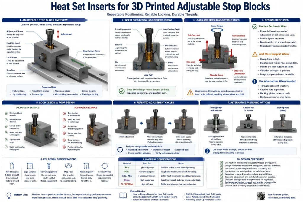
Why Adjustable Stop Blocks Need Careful Insert Design
Adjustable stop blocks often use screws as positioning or locking elements. The screw may push against another surface, lock a sliding element, or hold a stop plate in place. Each adjustment cycle applies torque and localized load to the insert and printed boss.
If the insert is weak, the screw may loosen or spin the insert. If the stop face deforms, the reference position changes. If the boss creeps under preload, the stop may slowly drift. If the screw bottoms out before clamping, the stop may feel tight but fail to hold position.
For adjustable stop blocks, the insert should be treated as part of a repeatable positioning system, not only as a convenient metal thread.
Common Use Cases
3D printed adjustable stop blocks are common in fixtures, jigs, small machines, assembly aids, camera rigs, robotics setups, sensor fixtures, and prototype tooling.
- fixture stop blocks
- adjustable workpiece stops
- limit blocks for sliding parts
- alignment stops
- machine travel limit stops
- sensor positioning stops
- camera rig adjustment stops
- robot joint travel limit blocks
- assembly fixture reference stops
- repeatable setup blocks
- locking blocks for rails or slots
- prototype tooling stops
For related fixture applications, see Heat Set Inserts in 3D Printed Industrial Fixtures, Heat Set Inserts in 3D Printed CNC Fixture Plates, and Heat Set Inserts for Printed Jigs with Replaceable Wear Plates.
How Adjustable Stop Loads Affect Inserts
Adjustable stop blocks usually experience repeated tightening and small positional loads rather than one-time assembly. A screw may be turned many times to set a position, lock a stop, or adjust a limit. This repeated use makes thread durability important.
Common loads include:
- screw tightening torque
- axial preload into the insert
- side load from a sliding part hitting the stop
- localized pressure at the stop face
- vibration from machines or moving parts
- repeated adjustment cycles
- creep under sustained screw pressure
- impact if the stop is hit repeatedly
The insert provides durable threads, but the printed block controls whether the stop position remains stable.
Insert Locations in Adjustable Stop Blocks
Heat set inserts can be used in several places inside an adjustable stop block. The best location depends on whether the screw adjusts position, locks the block, or holds a replaceable stop face.
Common insert locations include:
- adjustment screw threads
- lock screw threads
- replaceable stop face screws
- slot clamp screws
- rail locking screws
- fine adjustment screw supports
- mounting screws for stop blocks
- service screws for removable stop components
The insert should be placed so screw load transfers into the printed body instead of bending a thin wall or pulling on a weak boss.
Adjustment Screw vs Lock Screw
An adjustable stop may use one screw to set position and another screw to lock it. These two screws do different jobs and may need different insert support.
| Screw Type | Main Function | Insert Design Priority |
|---|---|---|
| Adjustment screw | Sets the stop position or travel limit | Thread smoothness, repeatability, alignment, low backlash |
| Lock screw | Holds the stop after adjustment | Torque resistance, preload stability, boss strength |
| Mounting screw | Attaches the stop block to a fixture or frame | Pull-out strength, screw engagement, load path |
| Replaceable face screw | Holds a wear surface or stop pad | Serviceability, seating depth, repeated assembly |
Trying to make one screw do all jobs can work in simple fixtures, but higher repeatability usually benefits from separating adjustment, locking, and load-bearing functions.
Boss Design for Adjustable Stop Blocks
The insert boss must survive repeated screw torque and preload. If the insert is used for a lock screw, the boss may see frequent tightening. If the insert is used for an adjustment screw, thread alignment and seating stability become especially important.
A good insert boss for adjustable stop blocks should provide:
- enough boss outside diameter
- enough wall thickness around the insert
- enough depth for insert seating
- proper screw engagement length
- fillets at boss transitions
- ribs or thick geometry behind the boss
- edge distance from slots, stop faces, and cutouts
- print orientation that resists splitting under screw torque
- alignment with the adjustment or locking direction
For boss geometry, see How to Design Bosses for Heat Set Inserts, Boss OD Ratio for Heat Set Inserts in 3D Printed Parts, and Heat Set Insert Minimum Wall Thickness Reference for 3D Printed Parts.
Screw Engagement and Position Stability
Adjustable stop blocks often depend on screw position. If the screw engagement is too short, the screw may wobble, loosen, or wear the insert. If the screw is too long, it may bottom out before the stop is locked. If the insert is misaligned, the screw may shift the stop position as it tightens.
Check the final stack-up:
- screw length
- insert seating depth
- usable thread engagement
- bottom clearance
- adjustment travel
- lock screw preload
- contact point at the stop face
- whether the screw axis matches the intended force direction
For screw engagement behavior, see Screw Engagement Length for Heat Set Inserts in 3D Printed Parts. For stack-up planning, see Heat Set Insert Assembly Stack-Up Reference for 3D Printed Parts.
Stop Face Deformation
The stop face is often more important than the insert. If the stop face dents, wears, creeps, or flexes, the reference position changes even if the insert remains strong.
Stop face deformation can happen when:
- a hard part repeatedly hits a soft printed stop
- a set screw creates a small pressure point
- the stop face is too thin
- the material creeps under sustained load
- the stop block sees vibration or impact
- the screw load is concentrated in a small area
- the printed layers are oriented poorly for the contact direction
Useful improvements include larger stop faces, replaceable pads, metal contact plates, washers, wear strips, or geometry that supports the stop surface from behind.
Repeated Adjustment Cycles
Adjustable stop blocks are often adjusted repeatedly. Heat set inserts help because the screw engages metal threads instead of wearing plastic threads. But repeated adjustment still affects the printed boss and stop face.
Repeated cycles can cause:
- insert spin during tightening
- thread wear if the insert is damaged
- boss cracking around the insert
- preload loss in lock screws
- stop face indentation
- position drift after vibration
- adjustment screw wobble
- slot or guide wear
- backlash in the adjustment system
For frequent service decisions, see Should I Use Heat Set Inserts for Parts That Need Frequent Disassembly?.
Through-Bolts and Captive Nuts for Adjustable Stops
Some adjustable stop blocks should use through-bolts, captive nuts, or metal plates instead of heat set inserts. This is especially true when the stop carries high load, sees impact, or must hold a position over many cycles.
Consider alternatives when:
- the stop is load-bearing
- the stop face receives repeated impact
- the insert would be close to an edge or slot
- the lock screw needs high preload
- the boss cannot be reinforced enough
- the stop must be field-serviceable
- the thread must be replaceable
- the adjustment screw needs a stronger metal support
For through-bolt decisions, see Should I Use Through-Bolts Instead of Heat Set Inserts in 3D Printed Parts?.
Material Considerations
Material choice affects both insert strength and stop accuracy. A stiff material may hold position well but crack near bosses. A tough material may resist impact but creep under preload.
| Material | Adjustable Stop Behavior | Insert Design Note |
|---|---|---|
| PLA | Stiff and dimensionally stable, but brittle under impact | Good for light stops; use fillets and avoid high impact loads. |
| PETG | Tough, but may creep under sustained screw pressure | Check long-term position drift and lock screw preload. |
| ABS / ASA | Useful for functional fixtures with better heat tolerance | Check layer adhesion and boss support. |
| Nylon | Tough and impact-resistant, but may creep | Use metal contact faces or locating geometry for repeatability. |
| Fiber-filled materials | Stiff and stable, but stress concentration matters | Use smooth transitions, reinforced bosses, and tested insert holes. |
For material comparison, see PLA vs PETG vs ABS for Threaded Inserts and Layer Adhesion and Heat Set Insert Strength in 3D Printed Parts.
Print Orientation and Repeatability
Print orientation affects whether the stop block holds position. If the insert boss or stop face is loaded across weak layer lines, the block may crack, flex, or drift.
Print orientation affects:
- boss splitting
- insert pull-out
- thread alignment
- stop face wear
- impact resistance
- position repeatability
- long-term creep direction
For adjustable stops, print orientation should be selected around the expected screw force and stop contact direction, not only print convenience.
Common Failure Modes
Adjustable stop blocks usually fail by losing position before they fail visibly. The screw may still turn, and the insert may still hold, but the stop reference may no longer be repeatable.
- insert spin during lock screw tightening
- boss cracking near the adjustment screw
- stop face indentation
- position drift after vibration
- set screw damage to printed surface
- screw bottoming out before locking
- thread misalignment
- boss creep under sustained preload
- slot wear around a movable stop
- adjustment backlash
For related failure explanations, see Why Do Heat Set Inserts Spin in 3D Printed Parts?, Why Do Bosses Crack Around Heat Set Inserts?, and Why Does Screw Preload Drop in 3D Printed Insert Joints?.
Testing Adjustable Stop Blocks
Adjustable stop blocks should be tested for repeatability, not only strength. A stop that survives tightening but shifts position after ten cycles may not be reliable for fixture work.
A useful test should include:
- final printed material
- final insert type and screw size
- final adjustment screw length
- repeated adjustment cycles
- lock screw torque
- impact or contact load if relevant
- checking for position drift
- checking for stop face indentation
- checking insert spin after repeated tightening
- checking whether the stop returns to the same reference position
Design Checklist
- Use heat set inserts when adjustment or locking screws need reusable metal threads.
- Separate adjustment, locking, and load-bearing functions when repeatability matters.
- Reinforce insert bosses with enough wall thickness, ribs, and fillets.
- Keep inserts away from slots, split lines, edges, and thin tabs.
- Check screw length to prevent bottoming before locking or clamping.
- Use replaceable stop faces or metal pads when contact wear matters.
- Use through-bolts or captive nuts when lock loads are high.
- Choose print orientation for screw force and stop contact direction.
- Test repeated adjustment cycles and position drift.
- Do not assume metal threads guarantee repeatable stop position.
Related Engineering Guides
- How to Choose Heat Set Inserts for 3D Printed Parts
- Screw Engagement Length for Heat Set Inserts in 3D Printed Parts
- Torque Resistance of Heat Set Inserts in 3D Printed Parts
- How to Design Bosses for Heat Set Inserts
- Pull-Out Strength of Heat Set Inserts in 3D Printed Parts
- Layer Adhesion and Heat Set Insert Strength in 3D Printed Parts
Related Selection Questions
- Should I Use Heat Set Inserts for Parts That Need Frequent Disassembly?
- Should I Use Through-Bolts Instead of Heat Set Inserts in 3D Printed Parts?
- Should I Use Heat Set Inserts in Load-Bearing 3D Printed Parts?
Related Applications
- Heat Set Inserts in 3D Printed Industrial Fixtures
- Heat Set Inserts in 3D Printed CNC Fixture Plates
- Heat Set Inserts for 3D Printed Clamp Blocks
- Heat Set Inserts for Adjustable Camera and Sensor Mounts
FAQ
Are heat set inserts useful in 3D printed adjustable stop blocks?
Yes. They are useful when adjustment screws, lock screws, or replaceable stop faces need reusable metal threads. The printed stop block still needs reinforced bosses and stable stop geometry.
What is the main risk in adjustable stop blocks?
The main risk is position drift. The insert may hold the screw, but the stop face, boss, or printed body may deform, creep, or shift after repeated adjustment cycles.
Should adjustment screws and lock screws use separate inserts?
They can, especially when repeatability matters. Separating adjustment and locking functions can reduce backlash, improve position control, and reduce stress on a single insert boss.
When should a stop block use a through-bolt or captive nut?
Use through-bolts or captive nuts when lock loads are high, impact is expected, the boss is weak, the stop must be field-serviceable, or the thread needs to be replaceable.
How do I make a printed stop block more repeatable?
Use reinforced bosses, enough screw engagement, stable stop faces, metal contact pads if needed, good print orientation, separate locking geometry, and repeated-cycle testing.