
Should I use heat set inserts in load-bearing 3D printed parts? Heat set inserts can be used in load-bearing 3D printed parts, but they should not be treated as the only source of strength. The insert provides a durable metal thread. The printed boss, wall thickness, edge distance, material, print orientation, layer adhesion, screw preload, and load path determine whether the joint can actually carry load.
A brass insert can make a screw joint more serviceable and more durable than plastic threads, but it does not turn weak printed geometry into a structural metal part. If the surrounding plastic fails, the insert will fail with it.
For load-bearing assemblies, heat set inserts should be designed as part of a complete fastening structure, not as isolated threaded holes.
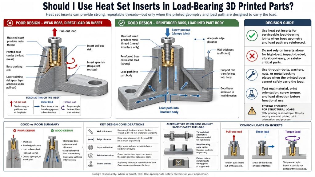
Short Answer
Use heat set inserts in load-bearing printed parts only when the boss and surrounding structure are designed for the real load. Do not rely on the insert alone for structural strength. For high-load, safety-critical, impact-loaded, or long-term vibration assemblies, consider through-bolts, metal plates, captive nuts, embedded hardware, or mechanical testing.
| Load Situation | Insert Decision | Better Design Action |
|---|---|---|
| Light to moderate load with reinforced boss | Often acceptable | Use correct insert size, wall thickness, and screw engagement. |
| Repeated service or removable bracket | Good use case | Design for preload retention and torque resistance. |
| High pull-out load | Use with caution | Check boss depth, insert length, material, and load direction. |
| Impact or vibration load | High risk without testing | Add ribs, washers, metal backing, or through-fasteners. |
| Safety-critical structural joint | Do not rely on inserts alone | Use validated mechanical design and physical testing. |
What Heat Set Inserts Actually Do
A heat set insert creates a reusable metal thread inside a printed part. This helps when screws need to be tightened, removed, and reinstalled without wearing out plastic threads.
Heat set inserts are useful for:
- repeated assembly
- serviceable panels
- removable brackets
- fixtures and jigs
- machine accessories
- motor mounts
- electronics enclosures
- robotics assemblies
- mechanical covers
- small-batch functional parts
But the insert only improves the thread interface. The printed part still carries the load. If the boss is thin, close to an edge, poorly printed, or loaded in the wrong direction, the insert can spin, crack the boss, or pull out.
For general insert selection, see How to Choose Heat Set Inserts for 3D Printed Parts.
Load-Bearing Does Not Mean One Thing
Load-bearing is a broad term. A small sensor bracket carrying its own weight is very different from a fixture clamp, a motor mount, or a structural robot joint.
Before choosing heat set inserts, identify the type of load:
- Pull-out load: the screw tries to pull the insert out of the boss.
- Shear load: the joint is loaded sideways.
- Torque load: screw tightening or twisting tries to rotate the insert.
- Preload: the screw clamps parts together over time.
- Vibration: repeated motion can reduce preload and loosen joints.
- Impact: sudden loads can crack printed bosses.
- Creep: sustained load can deform PETG, nylon, and some other materials.
The insert size should be selected only after the load direction and load path are understood.
When Heat Set Inserts Are a Good Choice for Load-Bearing Parts
Heat set inserts can work well in load-bearing parts when the load is moderate, the boss is reinforced, and the joint is designed for the direction of force.
They are often useful when:
- the part needs reusable metal threads
- the joint will be assembled and disassembled repeatedly
- the boss has enough outside diameter and wall thickness
- the insert is far enough from edges and corners
- the screw preload is controlled
- the load path goes into the main printed body
- the part has ribs, pads, or reinforced mounting zones
- the material has adequate layer adhesion
- the joint can be tested under real load
For repeated assembly behavior, see Heat Set Inserts for Repeated Assembly in 3D Printed Parts.
When Heat Set Inserts Are Not Enough
Heat set inserts are not enough when the printed geometry cannot support the load. In those cases, the insert may remain intact while the plastic around it cracks, splits, creeps, or pulls apart.
Heat set inserts alone are usually not enough when:
- the joint is safety-critical
- the load is high and continuous
- the part sees impact or shock
- the part sees strong vibration
- the insert is near an edge or thin wall
- the boss has poor layer orientation
- the screw preload must stay stable for a long time
- the material is creep-prone under load
- failure would damage equipment or create danger
For these cases, consider through-bolts, washers, metal backing plates, embedded nuts, larger printed bosses, ribs, thicker walls, or a hybrid printed-and-metal structure.
The Boss Carries the Real Load
The boss is the printed structure around the insert. In load-bearing parts, the boss is often more important than the insert itself.
A good load-bearing boss should provide:
- enough boss outside diameter
- enough wall thickness around the insert
- enough insert depth
- proper screw engagement
- fillets at the boss base
- ribs or thick geometry behind the boss
- enough distance from edges and corners
- a load path into the main part body
- print orientation that resists splitting
For boss geometry, see How to Design Bosses for Heat Set Inserts, Boss OD Ratio for Heat Set Inserts in 3D Printed Parts, and Heat Set Insert Minimum Wall Thickness Reference for 3D Printed Parts.
Pull-Out Load
Pull-out load happens when the screw tries to pull the insert out of the printed boss. This is one of the most important load cases for heat set inserts.
Pull-out resistance depends on:
- insert length
- insert outer texture
- pilot hole fit
- boss diameter
- wall thickness
- material behavior
- layer adhesion
- installation quality
- load direction
- distance from edges
A larger or longer insert can help only when the boss has enough material to support it. A long insert in a weak boss is just a deeper way to break the same part.
For pull-out behavior, see Pull-Out Strength of Heat Set Inserts in 3D Printed Parts.
Torque Load
Torque load happens during screw tightening or when the assembly applies twisting force to the insert. If the insert does not have enough grip, it may rotate inside the boss.
Torque resistance depends on:
- pilot hole size
- insert knurl geometry
- boss wall thickness
- material flow during installation
- installation temperature
- screw tightening torque
- boss support and edge distance
For torque behavior, see Torque Resistance of Heat Set Inserts in 3D Printed Parts and Heat Set Insert Torque Range Reference for 3D Printed Parts.
Shear and Side Loads
Heat set inserts are often used with screws that clamp two parts together. In many load-bearing assemblies, the screw should not be the only feature resisting shear. The printed geometry should include shoulders, pockets, tabs, dowels, ribs, or contact surfaces that help transfer side load.
If the insert is asked to resist side load by itself, the boss may bend, crack, or loosen over time. This is especially common in brackets, fixtures, motor mounts, and robotic joints.
Good shear load design often uses:
- locating shoulders
- mechanical stops
- large flat contact surfaces
- ribs behind the boss
- multiple fasteners
- washers or metal plates
- through-bolts for high-load cases
A screw joint should clamp. The printed structure should carry as much load path as possible.
Vibration and Long-Term Preload
Load-bearing parts often fail slowly through vibration, preload loss, or material creep. The insert may not pull out immediately, but the screw joint can loosen over time.
This is important in:
- motor mounts
- robot joints
- machine brackets
- fixture plates
- moving assemblies
- repeated service panels
- transported equipment
For vibration-related applications, see Heat Set Inserts for High-Vibration Motor Mounting Brackets. For vibration failure behavior, see Why Do Heat Set Inserts Fail Under Vibration?.
Material Choice Matters
Material choice affects whether a load-bearing insert joint survives. PLA, PETG, ABS, ASA, nylon, and fiber-filled materials behave differently under heat, preload, vibration, and long-term stress.
| Material | Load-Bearing Insert Behavior | Design Note |
|---|---|---|
| PLA | Stiff, but brittle and temperature-sensitive | Avoid impact, heat, and overtightening. Use generous boss support. |
| PETG | Tougher, but may creep under sustained preload | Check preload loss and bracket shift over time. |
| ABS / ASA | Useful for functional parts with better heat tolerance | Check layer adhesion and print quality around bosses. |
| Nylon | Tough and impact-resistant, but may creep | Use locating geometry and avoid relying only on screw preload. |
| Fiber-filled materials | Stiff and stable, but can be less forgiving around stress concentrations | Use fillets, ribs, and tested pilot hole dimensions. |
For material comparison, see PLA vs PETG vs ABS for Threaded Inserts and Layer Adhesion and Heat Set Insert Strength in 3D Printed Parts.
Print Orientation and Layer Adhesion
A load-bearing insert joint can fail through layer separation. This often happens when the insert pulls or twists in a direction that splits layers apart.
Print orientation affects:
- boss splitting
- pull-out strength
- torque resistance
- crack growth
- vibration durability
- edge breakout
If the load pulls across weak layer lines, the insert may fail even if the pilot hole and boss size look correct. For load-bearing parts, print orientation should be chosen around the expected load direction, not only surface finish or print convenience.
Insert Size Is Not the Whole Answer
Choosing a larger insert can increase fastening potential, but only if the printed geometry supports it. M4 or M5 inserts can be useful in larger brackets and fixtures, but they also need larger bosses, more wall thickness, and better load paths.
A well-supported M3 insert may be safer than an unsupported M5 insert in weak geometry.
For insert type references, see M3 Brass Heat Set Inserts for 3D Printed Parts, M4 Brass Heat Set Inserts for 3D Printed Parts, and M5 Brass Heat Set Inserts for 3D Printed Parts.
When to Use Through-Bolts Instead
Through-bolts are often better when the load is high, the part is safety-sensitive, or the printed boss cannot provide enough strength. A through-bolt transfers load through the part and can use washers, nuts, metal plates, or backing structures to spread force.
Consider through-bolts when:
- the joint is safety-critical
- the load is high or unpredictable
- the part sees impact
- the insert would be near an edge or thin wall
- the boss would be too small for the insert
- the joint needs metal-to-metal clamping
- failure would damage equipment
- testing shows insert pull-out or boss cracking
Heat set inserts are excellent for serviceable threads. Through-bolts may be better for structural load transfer.
Testing Load-Bearing Insert Joints
For load-bearing parts, design assumptions should be tested. A joint that feels strong during assembly may still fail under vibration, creep, impact, or repeated loading.
A useful test should include:
- real material and print orientation
- final insert type and size
- final screw length and washer stack-up
- controlled tightening torque
- pull-out or loading direction test
- vibration or repeated movement if relevant
- repeated assembly cycles if serviceable
- inspection for boss cracks or insert spin
- preload check after time under load
For stack-up planning, see Heat Set Insert Assembly Stack-Up Reference for 3D Printed Parts.
Common Mistakes
- using a larger insert without increasing boss size
- placing inserts near edges in load-bearing parts
- ignoring load direction
- relying on screw threads to carry shear load
- using inserts in thin walls without reinforcement
- ignoring layer orientation
- overtightening screws in printed bosses
- assuming brass insert strength equals joint strength
- not testing vibration or creep
- using inserts for safety-critical load without validation
For geometry boundary questions, see Should I Use Heat Set Inserts in Thin-Wall 3D Printed Parts? and Should Heat Set Inserts Be Used Near Edges or Corners in 3D Printed Parts?.
Practical Decision Rule
Use this simple rule:
- Use heat set inserts for serviceable load-bearing joints when the boss and load path are reinforced.
- Do not rely on inserts alone for high-load, impact-loaded, or safety-critical parts.
- Use through-bolts or metal backing when the printed boss cannot safely carry the load.
- Design the boss, wall thickness, edge distance, and print orientation around the real force direction.
- Test the joint when the part is functional, repeated-service, vibration-loaded, or load-bearing.
The insert is the thread. The printed structure is the bridge. A good bridge needs more than a strong bolt hole.
Related Engineering Guides
- How to Choose Heat Set Inserts for 3D Printed Parts
- Pull-Out Strength of Heat Set Inserts in 3D Printed Parts
- Torque Resistance of Heat Set Inserts in 3D Printed Parts
- How to Design Bosses for Heat Set Inserts
- Layer Adhesion and Heat Set Insert Strength in 3D Printed Parts
- Screw Engagement Length for Heat Set Inserts in 3D Printed Parts
Related Selection Questions
- Should I Use Heat Set Inserts in Thin-Wall 3D Printed Parts?
- Should Heat Set Inserts Be Used Near Edges or Corners in 3D Printed Parts?
- Should I Use Heat Set Inserts or Self-Tapping Screws in 3D Printed Parts?
Related Failure Questions
- Why Do Heat Set Inserts Fail Under Vibration?
- Why Do Heat Set Inserts Pull Out of 3D Printed Parts?
- Why Do Bosses Crack Around Heat Set Inserts?
- Why Does Screw Preload Drop in 3D Printed Insert Joints?
Related Applications
- Heat Set Inserts for High-Vibration Motor Mounting Brackets
- Heat Set Inserts in 3D Printed Industrial Fixtures
- Heat Set Inserts in 3D Printed CNC Fixture Plates
- Heat Set Inserts in Modular Robotics Systems
FAQ
Can heat set inserts be used in load-bearing 3D printed parts?
Yes, but only when the printed boss, wall thickness, material, layer adhesion, screw engagement, and load path are designed for the real load. The insert alone does not guarantee structural strength.
Are heat set inserts stronger than plastic threads for load-bearing parts?
They usually provide more durable threads than plastic threads, especially for repeated assembly. However, the printed boss and surrounding geometry still determine the joint strength.
Can heat set inserts replace through-bolts?
Not always. For high-load, impact-loaded, or safety-critical parts, through-bolts, washers, nuts, metal backing plates, or hybrid structures may be safer than relying on inserts in printed bosses.
What is the biggest risk in load-bearing insert joints?
The biggest risk is assuming the brass insert is the strong part. In many failures, the insert remains intact while the printed boss cracks, pulls out, creeps, or separates along layer lines.
Should load-bearing insert joints be tested?
Yes. Any functional load-bearing insert joint should be tested with the real material, print orientation, screw, insert, torque, load direction, and service conditions.