
M4 Brass Heat Set Inserts for 3D Printed Parts are medium-size threaded metal inserts used when printed parts need stronger reusable threads than small M2 or M3 joints can provide. They are commonly used in brackets, fixtures, motor mounts, mechanical panels, structural covers, robotic assemblies, and printed parts that require higher screw preload or more durable service cycles.
M4 inserts provide more thread engagement, more screw diameter, and more fastening margin than smaller inserts. However, they also require more printed material around the boss. An M4 insert is not automatically stronger if the printed part cannot support the larger boss, wall thickness, edge distance, installation heat, and tightening torque.
This page explains where M4 brass heat set inserts make sense, where they create risk, and how to design printed parts around their larger size.
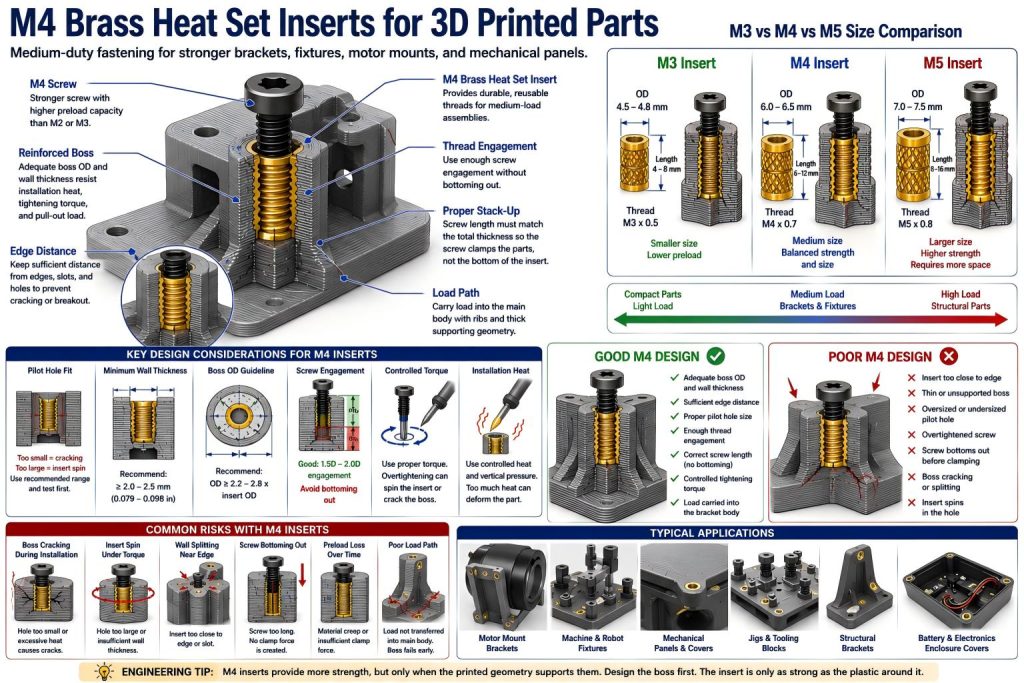
What Makes M4 Brass Heat Set Inserts Different?
M4 inserts sit between small electronic-scale inserts and heavier structural inserts. They are larger than M2 and M3 inserts, but still practical for many desktop 3D printed assemblies. Their main advantage is a stronger screw interface with more preload capacity, more thread engagement, and better tolerance for functional brackets.
The trade-off is geometry. An M4 insert needs a larger pilot hole, larger boss outside diameter, more wall thickness, and more spacing from edges and internal features. If the surrounding plastic is too thin, the larger insert may crack the boss, deform the wall, or create stress around the printed feature.
In practical terms, M4 is a good choice when the printed part has enough volume to support it. It is not a shortcut for weak geometry.
Common Use Cases
M4 brass heat set inserts are often used in 3D printed parts that need more fastening strength than small covers or electronics bosses, but do not require the large geometry of M5 inserts.
- mechanical brackets
- fixture plates
- motor mounting brackets
- robotic joint covers and service panels
- machine accessories
- tooling blocks
- structural covers
- mounting bosses for medium-load assemblies
- replaceable wear plates
- printed jigs and workholding accessories
- larger electronics or battery enclosure covers
- small-batch manufacturing fixtures
For related applications, see Heat Set Inserts for High-Vibration Motor Mounting Brackets, Heat Set Inserts for Printed Jigs with Replaceable Wear Plates, and Heat Set Inserts in 3D Printed Industrial Fixtures.
When M4 Inserts Are a Good Choice
M4 inserts are a good choice when the printed part has enough space for a properly supported boss and the joint needs more strength, preload, or service durability than an M3 joint can provide.
M4 inserts are often appropriate when:
- the printed part has enough boss diameter and wall thickness
- the screw joint carries moderate mechanical load
- the assembly may be removed and reinstalled many times
- the bracket needs more preload than an M3 screw can comfortably provide
- the part is used in a fixture, machine accessory, or mechanical panel
- the insert is not too close to an edge, slot, or thin wall
- the design can tolerate the larger screw head and washer area
- the printed material has enough layer adhesion and heat tolerance
For repeated assembly behavior, see Heat Set Inserts for Repeated Assembly in 3D Printed Parts.
When M4 Inserts May Be Too Large
M4 inserts become risky when the printed geometry is not large enough to support them. A larger insert can create more stress during installation and tightening. If the boss is undersized, M4 may perform worse than a well-supported M3 insert.
M4 inserts may be a poor choice when:
- the boss outside diameter is too small
- the insert sits near a thin edge or corner
- the part has narrow ribs, slots, or cutouts near the boss
- the printed wall cannot support installation heat
- the screw torque needed for M4 exceeds what the plastic can tolerate
- the part is thin and cannot provide enough seating depth
- the larger screw head interferes with the assembly
- the joint only carries light load and M3 is already sufficient
The safest choice is not always the largest insert. The best choice is the insert size that matches the printed geometry and load path.
M4 vs M3 vs M5 Heat Set Inserts
M4 is often selected when M3 feels too small but M5 is too large for the printed part. This makes M4 a useful middle-ground size for medium-duty printed assemblies.
| Feature | M3 Insert | M4 Insert | M5 Insert |
|---|---|---|---|
| Typical use | General brackets, covers, electronics, small assemblies | Fixtures, motor brackets, mechanical panels, medium-load joints | Large fixtures, heavy brackets, structural mounting |
| Space requirement | Moderate | Higher | Highest |
| Boss size requirement | Moderate | Larger boss needed | Very large boss needed |
| Preload capacity | Moderate | Higher | Highest if geometry supports it |
| Design risk | Usually forgiving | Boss cracking if geometry is undersized | High stress if used in weak printed geometry |
| Best design use | General-purpose fastening | Medium-duty mechanical fastening | Large structural fastening with enough material support |
For M3-specific reference content, see M3 Brass Heat Set Inserts for 3D Printed Parts and M3 Heat Set Insert Dimensions Reference. For M4 dimensional planning, see M4 Heat Set Insert Dimensions Reference for 3D Printed Parts.
Boss Design for M4 Inserts
The boss around an M4 insert must be treated as a real structural feature. Because the insert is larger, the boss must resist installation heat, radial expansion, screw tightening torque, pull-out load, and long-term clamp force.
A weak M4 boss can crack during installation, split during screw tightening, or deform under preload. This is especially common when designers enlarge a hole for M4 without enlarging the surrounding boss enough.
Important boss design practices include:
- use enough boss outside diameter around the insert
- maintain enough wall thickness between the insert and the boss edge
- avoid placing M4 inserts close to edges, slots, or sharp corners
- connect the boss to the main body with ribs or thick geometry
- use fillets where the boss meets the base
- avoid tall unsupported boss towers
- provide enough depth for the insert and screw engagement
- check print orientation so the boss does not split along layer lines
- avoid using M4 inserts in thin tabs unless the load is very light
For boss design, see How to Design Bosses for Heat Set Inserts and Boss OD Ratio for Heat Set Inserts in 3D Printed Parts.
Pilot Hole Size and Installation Sensitivity
M4 inserts require more heat and more displaced plastic than smaller inserts. If the pilot hole is too small, installation may create excessive outward pressure and crack the boss. If the pilot hole is too large, the insert may not grip enough plastic and can spin under screw torque.
Because M4 inserts are often used in mechanical brackets, users may tighten the screws more aggressively. This makes pilot hole accuracy and boss support especially important.
Good practice includes:
- printing test coupons before using a new insert style
- checking actual insert diameter instead of relying only on nominal size
- allowing for material shrinkage and slicer hole compensation
- using controlled installation temperature
- installing the insert square to the boss axis
- allowing the plastic to cool before applying screw load
- testing torque behavior before final assembly
For general hole sizing, see Heat Set Insert Hole Size Guide and Heat Set Insert Pilot Hole Tolerance Reference for 3D Printed Parts.
Installation Temperature and Seating Depth
M4 inserts need enough heat to soften the surrounding plastic, but too much heat can deform the boss, damage nearby features, or weaken the printed structure. The larger insert stores more heat than a small M2 or M3 insert, so overheating can affect a wider area.
Seating depth also matters. If the insert sits too proud, the mating part may not sit flat. If it is pushed too deep, the boss may deform, the screw stack-up may change, or the insert may interfere with internal geometry.
Important installation points include:
- use steady vertical pressure rather than forcing the insert
- keep the insert square during installation
- avoid pushing the insert below the intended seating depth
- protect nearby walls, slots, and cosmetic surfaces from heat distortion
- allow the insert area to cool before tightening the screw
- check that the mating part sits flat after installation
- check that the screw does not bottom out before clamping
For installation guidance, see Heat Set Insert Installation Temperature for 3D Printed Parts and Heat Set Insert Seating Depth Reference for 3D Printed Parts.
Screw Engagement and Torque Control
M4 screws can create more clamp force than smaller screws. This is useful for mechanical brackets and fixtures, but it also means the printed part must tolerate higher preload and tightening torque.
A screw that is too short may not engage enough thread. A screw that is too long may bottom out before the joint is clamped. A screw that is tightened too hard may spin the insert or crack the boss. M4 gives more fastening potential, but the plastic still sets the limit.
Good practice includes:
- checking screw length against the final assembly stack-up
- using enough thread engagement for the intended load
- avoiding screw bottoming before clamp force is created
- using washers when clamping softer printed surfaces
- using controlled torque for functional joints
- testing the joint after repeated assembly cycles
- checking for preload loss in PETG, nylon, and other creep-prone materials
For thread engagement, see Screw Engagement Length for Heat Set Inserts in 3D Printed Parts. For tightening behavior, see Heat Set Insert Torque Range Reference for 3D Printed Parts. For stack-up planning, see Heat Set Insert Assembly Stack-Up Reference for 3D Printed Parts.
Pull-Out Strength and Torque Resistance
M4 inserts can provide better pull-out and torque resistance than smaller inserts when the printed boss is properly designed. The larger contact area and deeper thread engagement can help, but only if enough printed material surrounds the insert.
If the boss is too thin, the larger insert can split the plastic. If the insert is too close to an edge, the load may tear out through the shortest wall. If layer adhesion is poor, the boss may separate along print layers even when the metal insert remains intact.
The design should treat pull-out and torque resistance as a system:
- insert size
- insert length
- boss outside diameter
- wall thickness
- edge distance
- material behavior
- print orientation
- screw engagement
- tightening torque
- load direction
For strength behavior, see Pull-Out Strength of Heat Set Inserts in 3D Printed Parts and Torque Resistance of Heat Set Inserts in 3D Printed Parts.
Material Considerations
Material choice affects how well the printed boss supports an M4 insert. Because M4 inserts are larger and can be tightened more strongly, material behavior becomes more important than it may be with smaller inserts.
| Material | M4 Insert Behavior | Design Note |
|---|---|---|
| PLA | Stiff and easy to print, but can crack around larger bosses | Use generous wall thickness and avoid overtightening. |
| PETG | Tougher than PLA, but may relax under higher screw preload | Check preload loss and bracket movement after service cycles. |
| ABS | Useful for functional brackets with better temperature tolerance | Check layer adhesion, boss support, and installation heat control. |
| ASA | Good for exposed or machine-adjacent mechanical parts | Maintain edge distance and avoid sharp stress paths near bosses. |
| Nylon | Tough and vibration-tolerant, but may creep under sustained preload | Use locating geometry and avoid relying only on screw friction. |
| Fiber-filled materials | Stiff and dimensionally stable, but can be less forgiving around stress concentrations | Use fillets, ribs, and enough boss volume around the insert. |
For material comparison, see PLA vs PETG vs ABS for Threaded Inserts and Layer Adhesion and Heat Set Insert Strength in 3D Printed Parts.
Common Failure Modes
M4 insert failures often happen when the larger insert is used without enough surrounding printed structure. The insert may be strong, but the printed boss becomes the weak link.
- boss cracking during installation
- insert spin during screw tightening
- wall splitting near the boss
- edge breakout from poor edge distance
- screw bottoming out before clamp force is created
- boss deformation from excessive installation heat
- preload loss in PETG or nylon
- layer separation around the insert boss
- fixture or bracket shifting after repeated assembly
- overconfidence in M4 size without enough boss support
For related failure explanations, see Why Do Heat Set Inserts Spin in 3D Printed Parts?, Why Do Bosses Crack Around Heat Set Inserts?, and Why Do Heat Set Inserts Fail Near Edges or Corners?.
Design Checklist
- Use M4 inserts for medium-duty brackets, fixtures, panels, and mechanical assemblies.
- Choose M3 instead when the printed part does not have enough room for a supported M4 boss.
- Choose M5 only when the structure has enough boss size, wall thickness, and load path support.
- Give the M4 insert enough boss outside diameter and wall thickness.
- Keep M4 inserts away from edges, slots, corners, and thin cutouts.
- Use ribs or thick geometry to connect the boss to the main part body.
- Test pilot holes before printing final parts.
- Install with controlled heat and straight vertical pressure.
- Check seating depth so the mating part can sit flat.
- Use correct screw length to avoid bottoming out.
- Do not overtighten M4 screws just because the insert is larger.
- Test preload retention under real assembly, vibration, and service conditions.
Related Engineering Guides
- How to Choose Heat Set Inserts for 3D Printed Parts
- Heat Set Insert Hole Size Guide
- How to Design Bosses for Heat Set Inserts
- Pull-Out Strength of Heat Set Inserts in 3D Printed Parts
- Torque Resistance of Heat Set Inserts in 3D Printed Parts
- Screw Engagement Length for Heat Set Inserts in 3D Printed Parts
- PLA vs PETG vs ABS for Threaded Inserts
Related Insert Type References
- M3 Brass Heat Set Inserts for 3D Printed Parts
- Short vs Long Heat Set Inserts for 3D Printed Parts
- Flanged vs Non-Flanged Heat Set Inserts for 3D Printed Parts
Related References
- M4 Heat Set Insert Dimensions Reference for 3D Printed Parts
- M5 Heat Set Insert Dimensions Reference for 3D Printed Parts
- Heat Set Insert Pilot Hole Tolerance Reference for 3D Printed Parts
- Heat Set Insert Minimum Wall Thickness Reference for 3D Printed Parts
- Heat Set Insert Edge Distance Reference for 3D Printed Parts
- Heat Set Insert Seating Depth Reference for 3D Printed Parts
- Heat Set Insert Assembly Stack-Up Reference for 3D Printed Parts
Related Applications
- Heat Set Inserts for High-Vibration Motor Mounting Brackets
- Heat Set Inserts for Printed Jigs with Replaceable Wear Plates
- Heat Set Inserts in 3D Printed Industrial Fixtures
- Heat Set Inserts in 3D Printed CNC Fixture Plates
- Heat Set Inserts in Modular Robotics Systems
FAQ
Are M4 brass heat set inserts stronger than M3 inserts?
They can provide more fastening margin than M3 inserts when the printed boss is large enough. If the boss is too small, too thin, or too close to an edge, an M4 insert may crack the printed part instead of making it stronger.
When should I choose M4 instead of M3 inserts?
Choose M4 when the part has enough material for a larger boss and the joint needs higher preload, better service durability, or more mechanical strength than M3 can provide.
When should I avoid M4 heat set inserts?
Avoid M4 inserts in thin walls, narrow tabs, small cosmetic parts, unsupported bosses, or areas close to edges and slots. In those cases, a well-supported M3 insert may be safer.
Can M4 inserts be used in motor mounts and fixtures?
Yes. M4 inserts are often useful in motor mounts, fixture plates, mechanical brackets, and service panels, but the printed boss must be designed for torque, preload, vibration, and load direction.
Do M4 inserts need more installation heat than M3 inserts?
Usually yes. M4 inserts are larger and require more heat to install properly, but overheating can deform the boss. Controlled temperature, straight insertion, and proper pilot hole size are important.