
Engineering References for Heat Set Inserts
Engineering references for heat set inserts help organize fastening dimensions, material compatibility, installation behavior, and structural selection data for 3D printed assemblies.
Insert products should not be selected only by thread size. In 3D printed parts, product dimensions, outer geometry, knurl pattern, insert length, pilot hole size, boss design, material behavior, and installation method all affect fastening reliability.
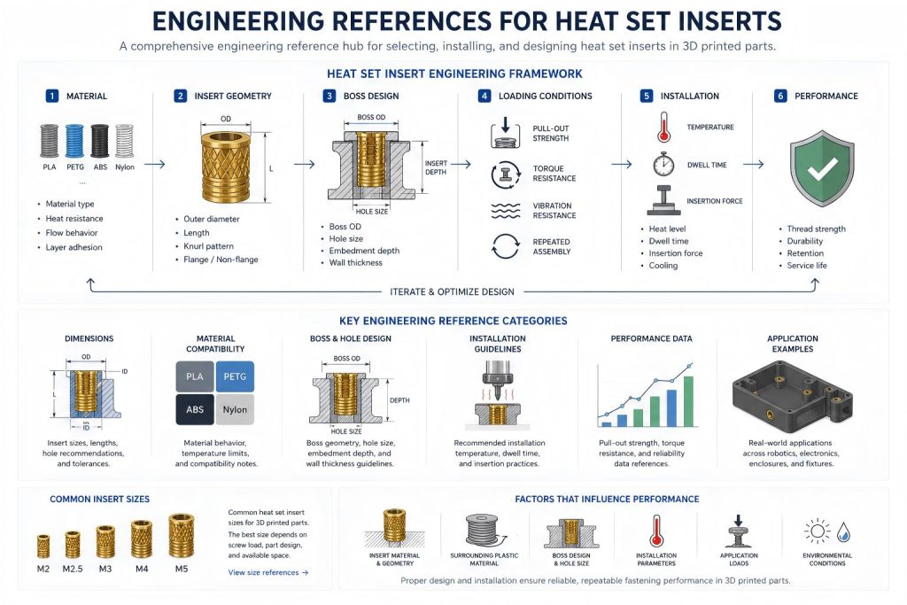
Reference Variables and Engineering Relationships
Heat set insert performance depends on multiple related engineering variables rather than thread size alone.
Insert outer diameter affects surrounding plastic displacement, boss wall thickness requirements, and pull-out resistance.
Insert length influences load transfer depth, screw engagement stability, and long-term fastening durability.
Pilot hole size affects plastic flow, insert retention, installation force, and torque resistance.
Boss geometry determines how fastening loads are distributed into the surrounding printed structure.
Material behavior influences thermal expansion, creep resistance, layer adhesion, and repeated assembly performance.
Installation temperature affects local material flow, insert seating quality, and structural stability around the insert cavity.
Engineering references should always be interpreted together with application conditions, fastening loads, and expected assembly cycles.
For how reference dimensions become practical design decisions, see the Heat Set Insert Hole Size Guide.
Heat Set Inserts
Heat set inserts are metal threaded components installed into thermoplastic printed parts using controlled heat and pressure.
They are commonly used when printed parts require repeatable screw assembly, improved thread durability, cleaner screw engagement, or stronger fastening points than printed plastic threads can provide.
Common heat set insert sizes for 3D printed parts include:
- M2
- M2.5
- M3
- M4
- M5
The best size depends on screw load, part size, wall thickness, insert depth, and available boss geometry.
Threaded Inserts
Threaded inserts provide durable internal threads for plastic parts, prototypes, fixtures, enclosures, robotic parts, and small batch printed assemblies.
Different insert types may use different installation methods, including heat installation, press-fit installation, molded-in use, or self-tapping engagement.
For 3D printed thermoplastics, heat set inserts are commonly used because heated installation allows the surrounding plastic to soften and flow around the insert geometry.
Product Selection Factors
When selecting inserts for 3D printed parts, the product should be evaluated together with the printed structure.
Engineering References for Heat Set Inserts
Engineering references for heat set inserts include insert dimensions, material compatibility, fastening structures, boss design relationships, installation behavior, and long-term assembly considerations for 3D printed parts.
Important product and design factors include:
- internal thread size
- insert outer diameter
- insert length
- knurl geometry
- recommended pilot hole size
- boss wall thickness
- printed material
- installation temperature
- screw load
- expected assembly cycles
A strong insert joint depends on both the metal insert and the surrounding printed plastic. Even a well-made insert can fail if the hole is oversized, the boss is too thin, or the material does not support the installation load.
Common Insert Sizes
M2 heat set inserts are often used in small electronics, compact enclosures, lightweight brackets, and low-load fastening points.
M2.5 Heat Set Insert Dimensions Reference A compact-size insert reference covering M2.5 heat set insert hole size, outside diameter, insert length, boss depth, wall thickness, screw engagement, and design limits for small 3D printed fastening structures.
M3 Heat Set Insert Dimensions Reference M3 inserts are one of the most common sizes for 3D printed assemblies, including electronics housings, printer parts, robotics brackets, fixtures, and functional prototypes.
M4 Heat Set Insert Dimensions Reference A structural-size insert reference covering M4 heat set insert hole size, outside diameter, insert length, boss depth, wall thickness, screw engagement, pull-out strength, torque resistance, and design limits for stronger 3D printed fastening structures.
M5 Heat Set Insert Dimensions Reference A large-size insert reference covering M5 heat set insert hole size, outside diameter, insert length, boss depth, wall thickness, screw engagement, pull-out strength, torque resistance, and structural design limits for stronger 3D printed fastening structures.
Heat Set Insert Hole Depth Chart A reference chart explaining heat set insert hole depth, insert length, boss depth, bottom clearance, screw engagement, blind holes, through holes, and common depth-related failures in 3D printed parts.
Boss OD Ratio for Heat Set Inserts A structural reference explaining how insert outside diameter, boss outside diameter, wall thickness, edge distance, pull-out strength, torque resistance, and material behavior affect heat set insert boss design in 3D printed parts.
Heat Set Insert Torque Range Reference for 3D Printed Parts A practical tightening torque reference for heat set insert assemblies, including torque sensitivity, insert spin risk, boss cracking, preload loss, and test coupon validation.
Heat Set Insert Edge Distance Reference for 3D Printed Parts A practical edge distance reference for heat set insert assemblies, covering remaining wall thickness, edge cracking, corner breakout, insert spin risk, and thin wall support.
Heat Set Insert Minimum Wall Thickness Reference for 3D Printed Parts A practical wall thickness reference for heat set insert assemblies, covering remaining plastic support, thin wall cracking, insert spin risk, pull-out support, and reinforced boss design.
Heat Set Insert Pilot Hole Tolerance Reference for 3D Printed Parts A practical pilot hole tolerance reference for heat set insert assemblies, covering printed hole variation, oversized holes, undersized holes, controlled interference, and test coupon validation.
Heat Set Insert Seating Depth Reference for 3D Printed Parts A practical seating depth reference for heat set insert assemblies, covering flush seating, proud inserts, over-insertion, bottoming out, thread access, and assembly surface contact.
Heat Set Insert Assembly Stack-Up Reference for 3D Printed Parts A practical assembly stack-up reference for heat set insert joints, covering screw length, mating part thickness, washers, seating depth, thread engagement, bottoming out, and preload loss.
Future Engineering References
Detailed product references for common insert sizes, including M2, M2.5, M3, M4, and M5, will be added as InsertGuide expands its engineering product database.
Future references may include insert dimensions, hole size ranges, boss design notes, material compatibility notes, and fastening application examples.
Reference Categories
InsertGuide will organize heat set insert products by thread size, insert geometry, and 3D printing application.
Future engineering reference categories may include:
- M2 heat set inserts
- M2.5 heat set inserts
- M3 heat set inserts
- M4 heat set inserts
- M5 heat set inserts
- assorted heat set insert kits
Each product reference will connect dimensions, recommended hole size, boss design notes, material compatibility, and application examples.
Related Engineering Recommendations
Recommended M3 Heat Set Inserts for PETG
Reference-to-Design Relationships
Thread size
→ insert outer diameter
→ pilot hole size
→ boss wall thickness
Insert length
→ load transfer depth
→ pull-out resistance
→ screw engagement stability
Hole tolerance
→ plastic flow
→ insert retention
→ torque resistance
Boss geometry
→ stress distribution
→ crack resistance
→ fastening durability
Material behavior
→ thermal stability
→ creep resistance
→ repeated assembly reliability
Installation temperature
→ material flow
→ insert seating quality
→ local structural integrity
Related Engineering Guides
- How to Choose Heat Set Inserts for 3D Printed Parts
- Heat Set Insert Hole Size Guide
- How to Design Bosses for Heat Set Inserts
- PLA vs PETG vs ABS for Threaded Inserts
- Why Heat Set Inserts Fail in 3D Printed Parts
- Pull-Out Strength of Heat Set Inserts in 3D Printed Parts
- Torque Resistance of Heat Set Inserts in 3D Printed Parts
- Layer Adhesion and Heat Set Insert Strength in 3D Printed Parts
- Heat Set Insert Installation Temperature for 3D Printed Parts
- Screw Engagement Length for Heat Set Inserts in 3D Printed Parts
- M2 Heat Set Insert Dimensions Reference
- M3 Heat Set Insert Dimensions Reference
- M3 Heat Set Insert Hole Size for 3D Printed Parts
- M3 Heat Set Insert Boss Design for 3D Printed Parts
- M3 Heat Set Insert Pull-Out Strength for 3D Printed Parts
- PLA vs PETG Fastening Behavior for Heat Set Inserts
- Heat Set Insert Torque Resistance in PETG vs PLA Parts
- Fiber-reinforced materials and engineering-grade nylons introduce additional fastening variables including thermal expansion differences, increased stiffness, altered layer adhesion behavior, and localized stress concentration around insert cavities.